System Architecture
After this chapter you can
- Trace a user request from DNS to a pod and back
Why this comes after the project overview#
The project overview said what each layer is for. It did not say how a request actually reaches the database — and that path is what every later decision gets measured against: which subnet a node sits in, which Service type is the right one, where TLS terminates, what the pipeline is allowed to reach.
In the capstone, this is the request path, from the ALB to mysql-0.
System Architecture is the blueprint of our platform. It defines how the network is structured, where the servers live, how the database is protected, and how traffic flows from a user's browser into our backend code.
The whole platform, on one page#
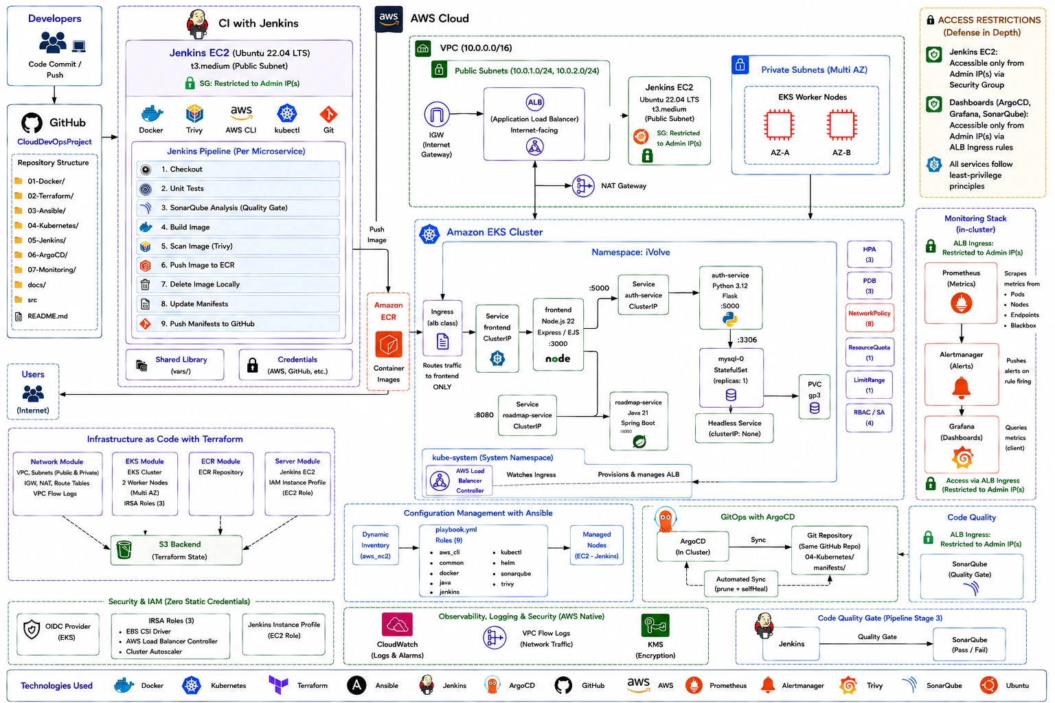
Do not try to absorb this yet. Right now, find four things on it — that is all this chapter needs from you:
- The path a request takes, bottom-left to middle: Users → ALB →
Ingress → the
frontendservice → the frontend pod. The ingress routes traffic to the frontend only; the other two services are reached from inside the cluster. Trace it with your finger. - The numbered column on the left. That is the build pipeline, stages 1 to 9 — checkout, tests, SonarQube gate, build, Trivy scan, push to ECR, then update and push the manifests. You will build it in Continuous Integration (Jenkins).
- The three microservices in the middle, each in a different language:
frontendon Node.js,auth-serviceon Python,roadmap-serviceon Java — plusmysql-0, a StatefulSet with a volume, because a database cannot be treated like a stateless pod. - The loop on the right, from pipeline stage 9 to the Git repository to Argo CD, which syncs it back into the cluster. Nothing deploys by being pushed at the cluster; the cluster pulls what Git says. That is the GitOps loop, and it is the most important idea here — The GitOps Philosophy is entirely about why the arrow points that way.
Come back to this diagram at the end of every phase. It will make more sense each time, and by the end of the Kubernetes phase you will be able to redraw it from memory — which is, incidentally, a very good interview answer.
This is the architecture of the Cloud DevOps Capstone, the project every roadmap here ends at. Every box on it exists in that repository — and if you would rather build it yourself than read it, the guided version starts from an empty workspace.
Level 1 — Beginner#
What is System Architecture?#
Imagine building a city. You don't just throw houses and roads everywhere. You need a city planner.
- You build a highway to let people in (The Internet / Load Balancer).
- You zone an area for shopping malls where people interact (Public Subnets).
- You zone a high-security area for banks where money is kept, and you put guards at the door (Private Subnets / Database).
Our System Architecture is the city plan for our software.
The Problem it Solves#
If you put your database on a public network, a hacker can easily try to guess the password. By designing a secure architecture, we place the database behind locked doors, where only our specific applications can talk to it.
ASCII Diagram: The City Plan#
       [ The Internet ]
              |
      (Front Gate / ALB)
              |
+-----------------------------+
|        PUBLIC ZONE          |
|  (Allows internet traffic)  |
|      [ NAT Gateway ]        |
+-----------------------------+
              |
+-----------------------------+
|        PRIVATE ZONE         |
| (No direct internet access) |
|   [ Kubernetes Servers ]    |
+-----------------------------+
              |
+-----------------------------+
|      TOP SECRET ZONE        |
|  (Only K8s can enter here)  |
|       [ Database ]          |
+-----------------------------+
Level 2 — Intermediate#
How it Works Internally (The Network Topology)#
Our architecture is deployed into AWS (Amazon Web Services). It uses a Virtual Private Cloud (VPC). A VPC is a logically isolated section of the AWS cloud.
Inside the VPC, we slice the IP addresses into smaller chunks called Subnets:
- Public Subnets: These subnets have a route to an Internet Gateway. The only thing we place here are Load Balancers (which receive traffic from users) and NAT Gateways (which allow our private servers to download software updates).
- Private Subnets: This is where the EKS worker nodes live. They have no public IP addresses — you cannot SSH into them from your house, and nothing on the internet can reach them directly. The database runs here too, as a pod on those same nodes.
The control plane appears in neither list, and that is worth pausing on. With EKS, AWS runs the API server, the scheduler and the etcd store in an account you never see. You get an endpoint, not servers — which is precisely what you are paying the control-plane fee for.
What Existed Before? (Flat Networks)#
In the old days, companies used "Flat Networks". Every server, including the database, had a public IP address. They relied entirely on software firewalls to block hackers. If a firewall crashed, the database was instantly exposed to the world. Our architecture prevents this at the hardware/routing layer.
The Request Flow#
- A user types
https://api.example.com. - DNS resolves to the AWS Application Load Balancer (ALB) in the Public Subnet.
- The ALB terminates the SSL certificate (decrypts the HTTPS traffic).
- The ALB forwards the request to an EKS worker node in a private subnet. That ALB was not clicked into existence: the AWS Load Balancer Controller watched the Ingress object and provisioned it.
- Kubernetes routes the traffic to the frontend pod — and only the frontend, because the Ingress has no rule for the other two services.
- The frontend calls
auth-serviceorroadmap-serviceby their internal DNS names, and those querymysql-0through its headless Service: a database pod with its own volume, in the same namespace, reachable only because a NetworkPolicy explicitly allows it.
Level 3 — Advanced#
Production Architecture: Multi-AZ High Availability#
An AWS Region (like us-east-1 in Virginia) is composed of multiple Availability Zones (AZs). An AZ is a distinct, physical data center with its own power grid and flood plains.
If we put all our servers in us-east-1a, and a fire destroys that building, our company goes offline.
To achieve High Availability, the Terraform network module distributes subnets across two AZs, and the EKS node group places workers in both.
Deep Dive: Analyzing the Network Configuration (Real Code)#
Let us look at how this is actually built. Open 02-Terraform/main.tf and find the network module call:
module "network" {
  source = "./modules/network"

  name_prefix        = local.name_prefix
  vpc_cidr           = var.vpc_cidr           # 10.0.0.0/16
  availability_zones = var.availability_zones # two of them
  enable_flow_logs   = true
  tags               = local.common_tags
}
Line-by-Line Breakdown:
vpc_cidr:10.0.0.0/16— 65,536 addresses. The module divides it into public subnets (10.0.1.0/24,10.0.2.0/24) for the ALB, the NAT Gateway and the Jenkins host, and private subnets for the worker nodes.availability_zones: a list like["us-east-1a", "us-east-1b"]. The module loops over it, so the subnet count follows from the list rather than being written out by hand.enable_flow_logs = true: captures metadata about every packet traversing the VPC. You will not look at it until the day you need to answer "did anything talk to that host", and on that day nothing else will do.
The NAT Gateway decision, which is worth understanding before you get the bill. A NAT Gateway is about $33/month each, and it lives in one AZ. Deploying one per AZ removes a single point of failure — if that AZ goes down, nodes in the others can still pull images. Deploying one for the whole VPC costs a third as much and makes that gateway's AZ a dependency for everybody.
This project runs a single NAT Gateway, because it is a learning environment where $66/month of redundancy buys nothing you will observe. In production, with revenue attached to uptime, the arithmetic reverses. What matters is that it is a decision with a number attached, rather than a default you inherited.
ASCII Diagram: Complete Network Flow#
   [ Internet ]
        |
        v
  [ Internet Gateway ]
        |
        v
  [ Application Load Balancer ]      created by the AWS Load Balancer
        |         |                  Controller, from the Ingress object
        |         |
  ┌─────|─────────|──────────────────────────────────────────────────┐
  │ VPC |10.0.0.0/16                                                 │
  │     v         v                                                  │
  │  ┌────────────────────────┐   ┌────────────────────────┐         │
  │  │ AZ us-east-1a          │   │ AZ us-east-1b          │         │
  │  │                        │   │                        │         │
  │  │  PUBLIC 10.0.1.0/24    │   │  PUBLIC 10.0.2.0/24    │         │
  │  │   [ NAT GW ]           │   │                        │         │
  │  │   [ Jenkins EC2 ]      │   │                        │         │
  │  │        ^               │   │                        │         │
  │  │        | egress only   │   │                        │         │
  │  │  PRIVATE               │   │  PRIVATE               │         │
  │  │   [ EKS worker node ]  │   │   [ EKS worker node ]  │         │
  │  │           ^            │   │           ^            │         │
  │  └───────────|────────────┘   └───────────|────────────┘         │
  └──────────────|───────────────────────────-|─────────────────────-┘
                 |                            |
                 +-------------+--------------+
                               |
                  [ EKS control plane — AWS-managed ]
                    you get an endpoint, not servers
Read the arrows carefully. Traffic comes in to the public subnets only. The private subnets have one outbound path — through the NAT gateway — and no inbound path at all. That asymmetry is the whole point of the layout: a worker node can fetch an image from ECR, and nothing on the internet can begin a conversation with it.
Level 4 — Enterprise#
Enterprise Patterns: Zero Trust and Compliance#
Fortune 500 companies operating under PCI DSS (Payment Card Industry) or HIPAA (Healthcare) compliance require strict network architectures.
- Egress Filtering: It is not enough to block inbound traffic. What if a server is infected with malware? The malware will try to phone home to a Command and Control (C2) server. In an enterprise environment, we replace standard AWS NAT Gateways with Transit Gateways attached to Next-Generation Firewalls (like Palo Alto) to perform Deep Packet Inspection (DPI) on outbound traffic.
- VPC Peering vs. Transit Gateway: As a company grows, it will have multiple VPCs (e.g., HR VPC, Finance VPC, Prod VPC). Connecting them via VPC Peering creates a complex, unmanageable "spiderweb" mesh. Enterprise architecture uses a Hub-and-Spoke model with a AWS Transit Gateway acting as the central router.
Platform Engineering: Scalability Limits#
When designing this architecture, we must calculate theoretical limits:
- A
/16VPC supports 65k IPs. - This cluster uses the AWS VPC CNI, which is the EKS default: every pod gets a real VPC IP address. That is a genuine advantage — a pod is routable from the rest of the network, security groups apply to it directly, and there is no encapsulation overhead to reason about when something is slow.
- The cost arrives at scale. Each node can only attach so many IPs, and in a large microservices estate you meet IP exhaustion long before you run out of CPU. Teams discover this when pods stop scheduling with no obvious resource pressure.
- The alternatives: an overlay CNI such as Calico gives pods addresses from a private range that never touches VPC space, trading a little encapsulation overhead for effectively unlimited pod IPs. Or you keep the VPC CNI and plan the addressing properly — prefix delegation, and a
/16you did not carve into/24s without thinking. - At this project's size the question is academic, which is exactly why it is worth knowing before it is not.
Interview Questions#
Beginner#
Q: What is the difference between a Public Subnet and a Private Subnet? A: A Public Subnet's route table has a route to an Internet Gateway, so an instance there with a public IP can be reached from the internet. A Private Subnet has no such route, so nothing on the internet can open a connection to it directly.
"Hidden" is the wrong word, though, and the distinction matters: a private instance is still reachable from elsewhere in the VPC, from a peered VPC, over VPN or Direct Connect, and — deliberately — from the load balancer in the public subnet. That last one is the entire architecture. What a private subnet removes is direct inbound reachability from the internet; security groups and NACLs still decide who may reach it from everywhere else.
Intermediate#
Q: Why do we put a NAT Gateway in a Public Subnet, but point Private Subnets to it? A: Private servers often need to download updates or API data from the internet. They send their request to the NAT (Network Address Translation) Gateway. The NAT Gateway, sitting in the Public Subnet, acts as a middleman. It forwards the request to the internet on behalf of the private server, and sends the response back, ensuring the private server's IP address is never exposed.
Senior#
Q: How do you secure database access across different VPCs without traversing the public internet? A: You can use VPC Peering (for simple 1-to-1 connections) or AWS Transit Gateway (for complex hub-and-spoke topologies). Both route traffic entirely across the internal AWS backbone. Alternatively, for exposing specific services, AWS PrivateLink allows one VPC to consume an endpoint in another VPC securely.
Principal/Architect#
Q: In an active-active multi-region architecture (e.g., us-east-1 and eu-west-1), how do you handle stateful data synchronization and routing?
A: Routing is handled via Route53 latency-based or geolocation routing. For stateful data, we must utilize global databases (like Amazon Aurora Global Database or DynamoDB Global Tables) which replicate storage synchronously or asynchronously at the block level. The architectural tradeoff is latency vs. consistency (CAP Theorem): synchronous replication guarantees consistency but adds high latency across regions, whereas asynchronous replication is fast but risks data loss during an abrupt region failure.
Contents | Platform Requirements |
Check yourself
4 questions from this chapter. Try answering before you look.
- What is the difference between a Public Subnet and a Private Subnet?
- Why do we put a NAT Gateway in a Public Subnet, but point Private Subnets to it?
- How do you secure database access across different VPCs without traversing the public internet?
- In an active-active multi-region architecture (e.g., `us-east-1` and `eu-west-1`), how do you handle stateful data synchronization and routing?